Lysozyme, with backbone shown as ribbon, active site region as
space-filling, and bound inhibitor as ball-&-stick models (PDB
1HEW)
(convergent stereo)
Revised 2008/07/10
Deep View provides powerful tools for turning its displays into stunning images that you can use in web pages, slide presentations, or journal articles. You can also turn Deep View scenes into input files for the program POV-Ray to produce images of the highest quality.
Technical note: These features of Deep View make use of the graphics library called OpenGL. To use these features, you must install OpenGL on your computer. If you do not have it, obtain it from the maker of your operating system. There is still a version of Deep View 3.6 that uses the Quickdraw3D graphics library, but versions 3.7 and later will be OpenGL only.
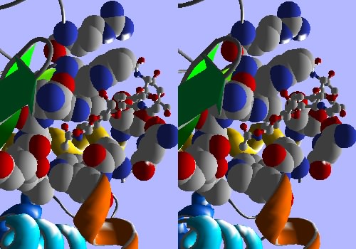
In this section, you will produce an image like the one shown below. In doing so, you will get a glimpse of the potential of Deep View to turn your most creative imaginings into beautiful and powerful illustrations.
Lysozyme, with backbone shown as ribbon, active site region as
space-filling, and bound inhibitor as ball-&-stick models (PDB
1HEW)
(convergent stereo)
If you have not worked through the first six sections of tutorial, please do so now. If you are an experienced user, please review the conventions used for specifying commands in these tutorials (see Overview under Contents in the left frame).
Start Deep View and open your old friend, PDB file 1HEW. Work in stereo if you are comfortable with it. Turn on stereo with <command - t>. Click here to learn stereo viewing.
In the Control Panel, scroll to the bottom of the residue list and select the tri-NAG inhibitor, groups 201-203. Press <return> to display only the three NAG units.
heading: labl
This action labels the selected groups only.
Arrange tri-NAG so that NAG201 is in front, with its C-6-OH pointing upward, and with NAG203 behind, above, and to the right of NAG201. Remove the labels by removing checkmarks in the labl column.
Select: Neighbors of Selected aa...
Make settings to select groups that are within 4 angstroms
of the picked atoms. Click OK and then press return to add the
newly selected groups to the display. Now the tri-NAG is surrounded
by all groups that have at least one atom within 4 angstroms of
it.
Tools: Compute H-bonds
You now see all hydrogen bonds involving the selected groups.
Arrange the image so that most of the protein-NAG H-bonds are easily
visible.
Prefs: 3D Rendering
"Rendering" means producing a three-dimensional image that looks
like a solid object, as opposed to the real-time wireframe images
that you use for exploring structure. The Rendering Preferences
dialog allows you to adjust many features of the rendered molecular
model. Make the following settings, and then click
OK.
Display: Render in Solid 3D
Now you see a lighted ball-and-stick model. Depending on the
speed of your computer, rendering this image may take some time (one
to two seconds on my '99 Mac G3 Powerbook). Rotate the model
slightly. Deep View switches to a simpler display when you move the
model, then renders again in the new position.
heading: ::
In the Control Panel, the column-heading symbol :: means
"dotted surfaces". Clicking this heading normally adds a surface to
all selected groups, but the rendered form of dotted surfaces in Deep
View is a space-filling model. You should see a little "v" just below
the ::, indicating that the type of surface displayed is van
der Waals (other types of surfaces are available in the little menu
under the :: symbol. Rendering a space-filling model may take
slightly longer (a good two seconds for me).
Now find the tri-NAG groups on the Control Panel, and remove the checkmarks from the :: column for these groups. You now see a ball-and-stick model of tri-NAG nestled in the space-filling pocket of neighbors. You also see the hydrogen bonds again. Move the model around a little, to get a view of the pocket similar to that in the figure above.
Select: Inverse Selection
This command "unselects" all groups that are currently selected, and
selects all remaining groups. So now the selection is all groups
except tri-NAG and its neighbors.
heading: ribn
You have added a ribbon model of the protein backbone for all
residues except those shown as solid models. Depending on how the
Ribbons Preferences are set, this ribbon has 1 to 5 strands. Zoom out
(unzoom?) until you can see the full model.
Prefs: Ribbons
This dialog controls properties of ribbons in real-time display
as well as in rendered models. Turn on Render as Solid Ribbon,
and set Quality to 2. Most of the other default settings are
satisfactory for this tutorial. But before you leave this dialog,
look at the other controls you can exert over the shape and color of
the ribbons. Click OK. After rendering (still about 2 seconds
for me) your model has solid ribbons, and is really beginning to look
like your target image.
In the Control Panel under the col (color) heading, click on the small black triangle to bring down a menu. Select ribbon. Now any color commands will color ribbons, but not other features.
Color: (Ribbon by) Secondary Structure
Succession
You have colored each secondary structural element of the
protein; the first one (nearest the N-terminus) is blue, the last
(C-terminal) one is red, and the ones in between are assigned other
colors spanning the visible spectrum.
Prefs: Colors
Click Background at the bottom of the dialog. You will get
your computer's standard color picker. Pick a light background color
of your choice. (I'm partial to light blues, perhaps because of those
enjoyable years in Chapel Hill.) Click OK on the color picker,
and then OK on the Rendering Preferences dialog. You model now
floats on the lighter background. By the way, you can also get to the
background color picker through the 3D Rendering Preferences. Either
way, this color remains as your background in both real-time and
rendered displays.
TIP: If you plan to print your images or turn them to GIF or JPEG files, and you want a pure white or pure black background, enter the background color as numbers to be sure your printer or file converter does not add little dytes of color in trying to make an almost-white or almost-black background. The values are as follows:
- for white, hue angle 0 degrees, saturation 0%, intensity 100%;
- for black, hue angle 0 degrees, saturation 0%, intensity 0%.
Prefs: 3D Lights
With this dialog, you control the number and positions of up to
three lights that illuminate the rendered model. Specify position
with x, y, and z, in angstroms, from the center
of the display. When you center the model with <=>, its
lighting center is (x, y, z) = (0, 0, 0).
Positive x is to the right, positive y upward, positive
z toward you. Specify intensities with a maximum of 1.00 (very
bright). For a soft, sidelighted effect, try these values for Light
#1: -10, 0, 0, with intensity 0.001. Turn on Cast Shadows for
Light #1. Click OK.
Now arrange the model in a pleasing position, perhaps zooming in to cut off some of the ribbons, giving a close-up view that makes you feel like you should be wary of that hungry active site.
Save: Image or Save: Image (stereo)
Direct the file to a convenient location. The saved file is in
"pict" format (on a Mac, at least). It behaves well in image
processors like Canvas and Photoshop.
TIP: If you plan to insert your images into web pages, it's a good idea to render them at the same size you need for the page. Once a file is converted to GIF by your web-page maker, changing its size can degrade its quality. In Deep View, click on the Tool Bar's leftmost button (Display Window Attributes), and set the graphics window pixel size to exactly what you need for the web page, and click OK. Changing the window size will kick you out of 3D rendering, but just select it again, arrange your model, and save.ANOTHER TIP: Some web-page makers degrade the image when they convert to GIF. I get best results in web pages if I convert Deep View pict files to JPEG format using the image processing program Canvas. My web-page processor, Claris Home Page, will accept the JPEG image without modification, so its quality remains high.
Now import your newly created image into a word processor document or web page. You're on your way to making vivid illustrations to support your writing.
When you have time to play a little, go back to the lighting preferences dialog (Prefs: 3D Lights) and play around with multiple lights and shadows. You'll see that many startling effects that you see in published images are mostly a matter of lighting.